gOKAI WAMI
ME357 a1
Introduction
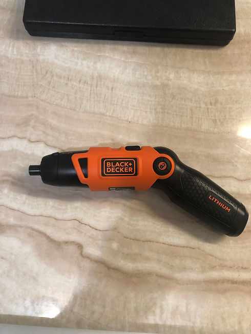
In this project, students were asked to break down and analyze the components of the B&D LI2000 Screwdriver to observe the structural design and purpose. The screwdriver was first disassembled and regrouped. The components could then be fully observed to identify its respective functions and its mistake-proof design. The gearbox is remodelled and reassembled through a CAD program (Computer-Aided Design) Creo Parametric 5000 to calculate its gear ratio and pitch diameter. The parts are measured and a full view can be represented on engineering drawings. Using the mechanism feature on Creo, a simulation of the working gearbox can be recreated. Diagrams are added to aid the understanding of the circuitry and functions each component serves. This website aims to help viewers visually comprehend how the screwdriver works the way it works.
SCREWDRIVER MECHANISM
GEARBOX CALCULATIONS
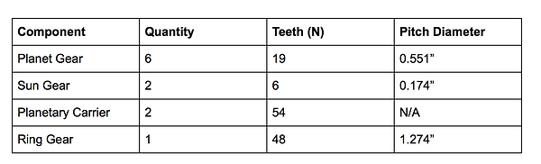
Note: The second sun gear is located on the end of the planetary carrier
Gear Ratio Calculation:
For epicyclic gear sets,
-
Let Npc be the number of teeths of a planetary carrier
-
Let Ns be the number of teeths of a sun gear
-
Let Nr be the number of teeths of a ring gear
-
Let Np be the number of teeths of a planet gear
Npc = Nr+Ns
Npc = 48+6=54 Teeth
When the sun gear (input) drives the planetary carrier (output) and when the ring gear is still,
Gear Ratio = Nouput/Ninput = Npc/Ns= 54/6 = 9:1 for a epicyclic gear set
However, since there are two stages in the gearbox,
Gear Ratio = 54/6*54/6 = 81:1 for the gearbox
Where,
output τ = input τ * 81
output ⍵ = input τ /81
Pitch Diameter Calculations:
Center Distance (Planet & Sun) = (Outer Diameter of Sun + Inner Diameter of Planet)/2
Outer Diameter of Sun= 0.235”
Inner Diameter of Planet= 0.490
CDplanet-sun = (0.235 + 0.490)/2 = 0.3625”
Center Distance (Planet & Planet) = (Outer Diameter of Planet + Inner Diameter of Planet)/2
Outer Diameter of Planet= 0.593”
Inner Diameter of Planet= 0.490”
CDplanet-planet = (0.593 + 0.490)/2 = 0.542”
Pitch Diameter of Sun = (2 * CDplanet-sun * Ns)/( Ns + Np)
PDsun = (2 * 0.3625 * 6)/(6+19) = 0.174”
Pitch Diameter of Planet = (2 * CDplanet-planet * Np)/(Ns + Np)
PDplanet = (2 * 0.3625 * 19)/(6 + 19) = 0.551”
Pitch Diameter of Ring = (1/2 * PDsun + PDplanet) * 2
PDring = (1/2 * 0.174 + 0.551) * 2 = 1.274”
Why use an epicyclic gear train?
The epicyclic gear train works brilliantly in this screwdriver because of its compact, efficient design. It is able to put out a large amount of output torque as seen by its 81:1 Gear Ratio and it does so without compromising space within the chassis since the planetary components share the same directional axis. Additionally, the multiple planet gears allow the distribution of the torque to be shared instead of putting a much higher torque onto a single gear. It becomes clear now why B&D decided to use an epicyclic gearbox for its screwdriver.
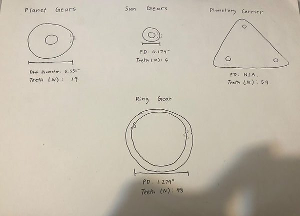
SKETCH OF DIFFERENT GEAR COMPONENTS
dESIGN FOR MANUFACTURING AND ASSEMBLY (DFMA)
Motor shell fitting in orange shell (Figure 2.1)
-
The one-half of the motor shell has an extruded part that sticks out which is purposely designed to be fit perfectly inside the orange shell. This allows the motor shell to not move when the motor is in operation. (As indicated by the circle)

Figure 2.1

FIGURE 2.5

FIGURE 2.6
MECHANICAL ELEMENTS EXPLANATION

DIAGRAM 1, ITEM 1

Takeaways
This project has taught me how the simplest functions a product demonstrates at the surface can be much more complex when the work behind it is shown. This was seen in the DFMA where components are included in the final design because it served a simple purpose yet the mechanisms needed to function required a lot of consideration. Another takeaway from this project was the experience with the assembly and mechanisms. Learning to use the mechanism in Creo is important in visually representing an assembly and it is essential to first see the product in action before finalizing and manufacturing. The aspect of the screwdriver being a real-life object has taught me that a lot of work is put into design and manufacturing.