Assignment #2 – Skateboard Deck Design
Goal:
The goal of this project is for students to create a design for a skateboard deck that could withstand a size-12 180 lb (800 N) person while having the deck be as light as possible. Additionally, students are to apply preliminary design knowledge, material selection, finite element analysis, and design optimization using different softwares and critical thinking.
Constraints:
The constraints that must be considered while designing the skateboard decks are of the following:
-
The board at any point or location exceeds a vertical displacement of 0.375 inches.
-
The factor of safety must be above 3 to account for any load variations.
Useful Information on Skateboard Decks:
A standard skateboard deck typically has a length of 28 inches. Additionally, since the deck is designed for an individual with size-12 feet, a width of 10 inches (longest longboard width on the market) should be used since a size 12 foot is approximately 11.25”. This makes it so that there is enough space for the user to balance on. An average skateboard deck is 8 inches wide, so this is a step up in design. A deck has a standard thickness of 0.7 inches. However, it is important to consider that skateboards come in all shapes, sizes, and variations (i.e. penny board being the smallest and longboard being the largest), so for the sake of simplicity, this project will first use an initial rectangular standard deck design with a length of 28 inches, a width of 10 inches, and a thickness of 0.7 inches.
There are several assumptions that need to be made when thinking about the deck design. The first assumption is that the board would not experience any torsional stress. This means that the flexural modulus would not have to be considered and that the user would not try to twist the deck when utilizing it. The second assumption that needs to be made is that the only force acting upon the deck is the vertical downwards force from the 180-lb or 800 N weight. The third assumption is that instead of the cross-sectional area of the force being applied on the area of the footprints itself, the entire area of the deck is considered in the manual calculations, however - this will not be the case in the SOLIDWORKS static study since the force is only applied to the footprints.
Material Selection:
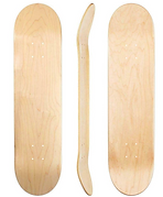
Image Source: https://www.longboarderlabs.com/product/cheap-blank-decks-natural-raw-7-75-8-0-8-25-and-8-5/
Note: The GRANTA Pine used in SOLIDWORKS has much weaker yield strength than the values used in GRANTA EduPack, as seen in the differences in figure 3 and figure 4. For the rest of the calculations, the yield strength of 36,128,528 Pa will be used instead of the 5*10^7 Pa used in the GRANTA EduPack.
SOLIDWORKS Static Load Analysis (Initial Design)
Initial Design (Rectangular)

Figure 6: The static study demonstrating the vertical displacement (Uy) of the board when a total of 800N is applied onto the board. As seen in the results of the static study, the maximum vertical displacement which is color-coded with dark blue is 6.387*10^-2in = 0.06387 inches, which is below the 0.375 inches constraint. So the material choice worked in having a vertical displacement below the 0.375 constraint.
Optimization of Design:
It is safe to say this initial design of the board works, but how can the board be further improved? A design study should be done on the thickness of the board to optimize the weight of the board, since the length and the width should not be changed (to fit with the standard skateboard size).
At the current design, the optimal thickness = 0.395 in, the weight of the deck is found to be 3.99 lb. Certain locations of the board can be removed to lessen weight. These locations are based on the static study stress plot from the initial design. Ideally, the stress is uniformly distributed everywhere throughout the board. This will be accomplished by incorporating mechanical shaping and then optimizing the dimensions
First Improvement
First Improvement (Adding Side Curves)

Figure 10: Adding a side curve on each side of the deck design to optimize material use with the dimensions 3.75 in by 20 in.
Final Improvement:
Second Improvement (Adding Holes)

Figure 14: The incorporation of the second geometry optimization to reduce the weight of the deck. By adding elliptical holes towards the red and yellow colored areas in the stress plot from the first geometry optimization, the material use can be lowered and the stress can be more uniformly distributed. The smaller ellipticals have a radius of 1.1 in and a length of 1.7 in. The large center elliptical has a radius and length of 2 and 2.5 in, respectively.
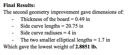
A manual calculation of the new design would be in order, but the design is too complex to solve. Let’s trust the value that SOLIDWORKS has provided.
Conclusion and Future Work:
At a weight of 2.8851 pounds, the design for the deck can be considered a success because the weight of a longboard - the design the deck is based off of, typically varies from 8-11 pounds. Assuming a longboard deck with 9.5 pound average weight, this makes the design of this deck 70% more efficient in weight. The success of this design can be attributed to GRANTA EduPack’s vast materials database which allowed for filtration of materials by observing the density and mechanical properties and then limiting the values to a specific range. SOLIDWORKS was used in the design as a means to visualize the design and then study the stress, strain, vertical displacement, and factor of safety. Additionally, SOLIDWORKS’ design study allowed for the dimensions to be modified such that the deck would be optimized to have the lowest weight possible yet still stay within the factor of safety of above 3 and vertical displacement constraints below 0.375 inches. Finally, by implementing design elements such as identifying areas where stress uniformity could be improved and then incorporating holes into the part then optimizing the area of the holes by design study so that the constraints would be satisfied.
An aspect that could be improved in future work is including the griptape into the deck design. The griptape and the adhesive attaching it to the rest of the board would add additional weight to the board although very little. Additionally, holes for the trucker bolts should be added to the design since that is where the deck would be attached to form a skateboard. Furthermore, the safety of the user should be considered when designing. This was not included in the design because chamfering the corners would increase the stress around the ends of the board. Another obstacle was the Granta Pine’s mechanical property values which differed in SOLIDWORKS and in GRANTA EduPack. This was seen with the 1.11*10^10 Pa value in the Young’s Modulus and 36,128,528 Pa in the yield strength in SOLIDWORKS, while in GRANTA EduPack, these values were 5.19865*10^8 Pa and 3,702,485 Pa, respectively. The difference is off by a magnitude of 20 in the Young’s Modulus and by an order of 10 in the Yield Strength. This is due to the inaccuracy of information in one of the software - most likely SOLIDWORKS since it is not a materials database. The stress calculated manually and in the static study differed since the stress was only applied to the area of the footprints while in the manual calculations, the stress was uniformly distributed across the cross-sectional area of the deck. Lastly, the stress calculations done manually for the material parameters was only for the shear stress. SOLIDWORKS uses von Mises stress which means it considers the stress components in all directions. This may be why the manual stress calculations differed from the SOLIDWORKS static study. Since the stress value is used in calculating other variables like the factor of safety and strain calculations, this may be why the manual and SOLIDWORKS values for the other values as well. However, the displacement values in both cases are within the same order of magnitude which means that the manual calculations could support the static study findings in that sense. Even though the design of the deck has many issues at hand, by the SOLIDWORKS results, the design fulfills all constraints and works as a skateboard deck that could hold its weight.
Technical Report PDF:
Citations:
-
BIOVIA, Dassault Systèmes, SOLIDWORKS Education, 2020, San Diego: Dassault Systèmes, Accessed March 1, 2021.
-
CES EduPack software, Granta Design Limited, Cambridge, UK, 2009, Accessed March 1, 2021
-
Mei, T. (n.d.). Blank skateboard deck dimensions. Retrieved March 04, 2021, from https://skatepaige.com/uncut-skateboard-blanks/skateboard-deck-dimensions.html